Monday 26 October 2009

USB Keyboard by Microcontroller with Embedded Hub Circuit

The Atmel sample version of the AT43USB326 contains firmware
that supports customization of the Vendor ID, Product ID,
String Descriptor and the keyboard matrix. This information
is stored in an external AT24C02A serial EEPROM.
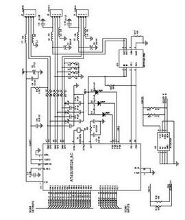


The Atmel AT43USB326 is an 8-bit microcontroller based on the
AVR RISC architecture. By executing powerful instructions in
a single clock cycle, the AT43USB326 achieves throughputs
approaching 12 MIPS. The AVR core combines a rich instruction
set with 32 general-purpose working registers. All 32 registers
are directly connected to the ALU allowing two independent
registers to be accessed in one single instruction executed in
one clock cycle. The resulting architecture is more code efficient
while achieving throughputs up to ten times faster than
conventional CISC microcontrollers.

Features
• AVR® 8-bit RISC Microcontroller with 83 ns Instruction Cycle Time
• USB Hub with One Attached and Two External Ports
• USB Keyboard Function with Three Programmable Endpoints
• 16 KB Program Memory, 512 Bytes Data SRAM
• 32 x 8 General-purpose Working Registers
• 32 Programmable I/O Port Pins
• Support for 18 x 8 Keyboard Matrix
• Keyboard Scan Inputs with Pull-up Resistor
• Four LED Driver Outputs
• One 8-bit Timer/Counter with Separate Pre-scaler
• External and Internal Interrupt Sources
• Programmable Watchdog Timer
• 6 MHz Oscillator with On-chip PLL
• 5V Operation with On-chip 3.3V Power Supply
• 48-lead LQFP Package

http://www.atmel.com/dyn/resources/prod_documents/doc3313.pdf

Read More......

Wednesday 8 April 2009

Programming the AVR microcontroller with GCC

The AVR 8-Bit RISC microcontroller from Atmel is a very common microcontroller. This microcontroller is one chip with EEPROM, Ram, Analog to Digital converter, a lot of digital input and output lines, timers, UART for RS 232 communication and many other things.
The best is however that a complete programming environment is available under Linux: You can program this microcontroller in C using GCC.


A lot of things have changed in the avr-libc development and the AT90S4433 microcontroller which I used in 2002 is no longer manufactured by Atmel. This is therefore an update of the March 2002 article. I will use libc-1.0.4 and the ATmega8 microcontroller.

This article shall be only an introduction and in a later series of articles we will again build interesting hardware but this time based on the ATmega8.
Many people where interested in microcontroller programming after the article which I wrote in 2002. However this first step to get the development environment up and running is the hardest. If something does not work then you have absolutely no clue where the fault is. Programmer cable wrong?? Circuit faulty? Installation incorrect? Parallelport disabled in bios? Kernel modules for ppdev compiled wrong? There can be a lot of reasons why things don't work

Read More......

Monday 4 August 2008

What is a PICmicro?

The PICmicro was originally designed around 1980 by General Instrument as a small, fast, inexpensive embedded microcontroller with strong I/O capabilities. PIC stands for "Peripheral Interface Controller". General Instrument recognized the potential for the little PIC and eventually spun off Microchip, headquartered in Chandler, AZ to fabricate and market the PICmicro.


The PICmicro has some advantages in many applications over the older chips such as the Intel 8048/8051/8052 and its derivatives, the Motorola MC6805/6hHC11, and many others. Its unusual architecture is ideally suited for embedded control. Nearly all instructions execute in the same number of clock cycles, which makes timing control much easier. The PICmicro is a RISC (Reduced Instruction Set Computer) design, with only thirty-odd instructions to remember; its code is extremely efficient, allowing the PIC to run with typically less program memory than its larger competitors.

Very important, though, is the low cost, high available clock speeds, small size, and incredible ease of use of the tiny PIC. For timing-insensitive designs, the oscillator can consist of a cheap RC network. Clock speeds can range from low speed to 20MHz. Versions of the various PICmicro families are available that are equipped with various combinations ROM, EPROM, OTP (One-Time Programmable) EPROM, EEPROM, and FLASH program and data memory. An 18-pin PICmicro typically devotes 13 of those pins to I/O, giving the designer two full 8-bit I/O ports and an interrupt. In many cases, designing with a PICmicro is much simpler and more efficient than using an older, larger embedded microprocessor.

SOURCE FROM: botkin.org

Read More......

Saturday 7 June 2008

PIC Microcontroller Introduction

A PIC microcontroller is a processor with built in memory and RAM and you can use it to control your projects (or build projects around it). So it saves you building a circuit that has separate external RAM, ROM and peripheral chips.


What this really means for you is that you have a very powerful device that has many useful built in modules e.g.

* EEPROM.
* Timers.
* Analogue comparators.
* UART.


Even with just these four modules (note these are just example modules - there are more) you can make up many projects e.g.:

* Frequency counter - using the internal timers and reporting through UART (RS232) or output to LCD.

* Capacitance meter - analogue comparator oscillator.

* Event timer - using internal timers.

* Event data logger -capturing analogue data using an internal ADC and using the internal EEPROM for storing data (using an external I2C for high data storage capacity.

* Servo controller (Control through UART) - using the internal PWM module or using a software created PWM.

The PIC Micro is one of the most popular microcontrollers and in case you were wondering the difference between a microprocessor and a microcontroller is that a microcontroller has an internal bus with in built memory and peripherals.

In fact the 8 pin (DIL) version of the 12F675 has an amazing number of internal peripherals. These are:

* Two timers.
* One 10bit ADC with 4 selectable inputs.
* An internal oscillator (or you can use an external crystal).
* An analogue comparator.
* 1024 words of program memory.
* 64 Bytes of RAM.
* 128 Bytes of EEPROM memory.
* External interrupt (as well as interrupts from internal peripherals).
* External crystal can go up to 20MHz.
* ICSP : PIC standard programming interface.

And all of these work from within an 8 pin DIL package!

In the mid-range devices the memory space ranges from 1k to 8k (18F parts have more) - this does not sound like a lot but the processor has an efficient instruction set and you can make useful projects even with 1k e.g. LM35 temperature sensing project that reports data to the serial port easily fits within 1k.

Features
In fact a PIC microcontroller is an amazingly powerful fully featured processor with internal RAM, EEROM FLASH memory and peripherals. One of the smallest ones occupies the space of a 555 timer but has a 10bit ADC, 1k of memory, 2 timers, high current I/O ports a comparator a watch dog timer... I could go on as there is more!
Programming
One of the most useful features of a PIC microcontroller is that you can re-program them as they use flash memory (if you choose a part with an F in the part number e.g. 12F675 not 12C509). You can also use the ICSP serial interface built into each PIC Microcontroller for programming and even do programming while it's still plugged into the circuit!

You can either program a PIC microcontroller using assembler or a high level language and I recommend using a high level language such as C as it is much easier to use (after an initial learning curve). Once you have learned the high level language you are not forced to use the same processor e.g. you could go to an AVR or Dallas microcontroller and still use the same high level language.
Input / Output - I/O
A PIC Microcontroller can control outputs and react to inputs e.g. you could drive a relay or read input buttons.

With the larger devices it's possible to drive LCDs or seven segment displays with very few control lines as all the work is done inside the PIC Micro.

Comparing a frequency counter to discrete web designs you'll find two or three chips for the microcontroller design and ten or more for a discrete design. So using them saves prototype design effort as you can use built in peripherals to take care of lots of the circuit operation.

Many now have a built in ADC so you can read analogue signal levels so you don't need to add an external devices e.g. you can read an LM35 temperature sensor directly with no interface logic.
Peripherals
The PIC microcontroller has many built in peripherals and this can make using them quite daunting at first which is why I have made this introductory page with a summary of each major peripheral block.

At the end is a short summary of the main devices used in projects shown on this site.

The best way to start is to learn about the main features of a chip and then begin to use each peripheral in a project. I think learning by doing is the best way.
Flash memory
This is the program storage area and gives you the most important benefit for using a PIC microcontroller - You program the device many times. Since when does anyone get a program right first time ?

Devices used in projects on this site can be re-programmed up to 100,000 times (probably more) as they use Flash memory - these have the letter F in the part name. You can get cheaper (OTP) devices but these are One-Time-Programmable; once programmed you can't program it again!
ICSP
In Circuit Serial Programming (ICSP) is the next most important benefit. Instead of transferring your chip from the programmer to the development board you just leave it in the board. By arranging the programming connections to your circuit correctly you won't need to remove the chip!

You can re-program the device while it's still in the circuit so once your programmer is setup you can leave it on the bench and test your programs without moving the chip around and it makes the whole process much easier.

Read More......

Sunday 11 May 2008

Fuzzy Logic and Neural Networks

Fuzzy Logic and neural networks are two design methods that are
coming into favor in embedded systems. The two methods are very
different from each other, from conception to implementation.
However, the advantages and disadvantages of the two can complement
each other.


The advantage of neural networks is that it is possible to design
them without completely understanding the underlying logical rules by
which they operate. The neural network designer applies a set of
inputs to the network and "trains" it to produce the required output.
The inputs must represent the behavior of the system that is being
programmed, and the outputs should match the desired result within
some margin of error. If the network's output does not agree with
the desired result, the structure of the neural network is altered
until it does. After training it is assumed that the network will
also produce the desired output, or something close to it, when it
presented with new and unknown data.

In contrast, a fuzzy-logic system can be precisely described. Before
a fuzzy control system is designed, its desired logical operation
must be analyzed and translated into fuzzy-logic rules. This is the
step where neural networks technology can be helpful to the
fuzzy-logic designer. The designer can first train a software neural
network to produce the desired output from a given set of inputs and
outputs and then use a software tool to extract the underlying rules
from the neural network. The extracted rules are translated into
fuzzy-logic rules.

Fuzzy logic is not a complete design solution. It supplements rather
than replaces traditional event control and PID (proportional,
integral, and derivate) control techniques. Fuzzy logic relies on
grade of membership and artifical intelligence techniques. It works
best when it is applied to non-linear systems with many inputs that
cannot be easily expressed in either mathematical equations used for
PID control or IF-THEN statements used for event control.

In an effort to change fuzzy logic from a "buzzword" (as it is in
most parts of the world) to a well established design method (as it
is in Japan), most manufacturers of microcontrollers have introduced
fuzzy logic software. Most software generates code for specific
microcontrollers, while other generates C code which can be compiled
for any microcontroller.

Read More......